
Let’s Make Some Music!
And for you internet trolls and memers…
Credit for both videos goes to Fabrício H. Franzoli at Franzoli Electronics. For more Telsa coil content check out his YouTube channel here and his Facebook group here.
Background.
When most of us think about the scientific concepts of electricity and power a few images often come to mind, home appliances with rubbery black plugs, the familiar three-pronged wall sockets that line the walls of our homes, or maybe even an image of an incandescent light bulb. It is certainly true that today power is distributed via wires and cables, however, every so often it’s important to expand our horizons by looking to the past. Surprisingly the groundwork for the extraordinary display of electricity and sound you just watched was laid over 100 years ago…
In 1900, an ambitious and now rather famous inventor and electrical engineer, Nikola Tesla, approached American financier and banker James Pierpont Morgan (J. P. Morgan) for the funds to develop a pair of wireless towers, one constructed on each side of the Atlantic.
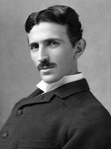
Nikola Tesla (1890)
The goal of Tesla’s endeavor was to transmit textual messages, voices, and facsimile images (fax images) to vessels at sea to gain such information as instantaneous stock quotes from the New York Stock Exchange. Although requesting $100,000 in funds and receiving a greater $150,000 from Morgan, Tesla became overly ambitious and greedy attempting to scale up his project to include global transmission of wireless power in hopes of beating out rival Guglielmo Marconi’s radio-based telegraphic communications system. This decision would prove to be fatal, as the funds required to build Tesla’s improved project would skyrocket to a staggering $450,000 (about $12,164,846 using a dollar estimate from 2016). Despite Morgan’s offer to invite other investors (a result of Morgan’s unwillingness to provide the greatly ballooned funds required by Tesla), Tesla was not able to get the necessary funding, and thus, Wardenclyffe Tower, the first tower constructed by Tesla in Shoreham, NY, was abandoned, fell into disrepair, and was demolished in 1915.
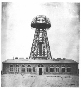
Wardenclyffe Tower (1904)
If Tesla had not been so greedy with regards to his endeavor we may have had noncommercial versions of a wireless text, voice, and image transmission system possibly as early as 1902 or 1903. However, the greater question that many of you are likely asking, (I know I was itching to ask the same question) “How was he planning to do it?” The invention employed has become a household name around the world, the Tesla coil.
A Tesla coil in its simplest form is something called a resonant transformer. For those of you that don’t know what a transformer is, it is a basic electronic device that transfers electrical energy via induction through a pair of coils usually wound around an iron-based or magnetic object. In the case of a resonant transformer, the point of the transformer is not to transfer but to store energy for short periods of time. The number of coils on the resonant transformer determines its overall capacitance, its ability to store charge. The summed coils act as a resonant circuit (LC circuit) meaning they are able to store electrical energy at a specific frequency. If the resonant transformer is driven by a radio frequency oscillator, an electronic circuit that can produce an electromagnetic signal in a periodic fashion, very high voltages (in some cases as high as millions of volts) can be generated with a relatively low current.
 So how did Tesla actually use the Tesla coil to transmit wireless power? Tesla found in his experiments that if a Tesla coil could be used to generate high voltages, then another coil tuned to the same frequency as the first could intercept the signal over relatively long distances. Even more fascinating for long range applications, Tesla hoped pulsed currents could be directed into the Earth itself and made to resonate at the proper frequency using a “grounded Tesla coil.” Tesla hoped that the electrical potential of the Earth itself would resonate at a standing wave worldwide. This would allow alternating current, current that travels in the form of a sinusoidal wave (reverses direction), to be distributed globally and intercepted using a simple capacitor based antenna tuned to the resonant frequency.
There are some drawbacks however to Tesla’s idea. First off, induction occurs over relatively short distances. As a result, there is not much hope for long range transmission via induction. Second, as we will see later with my low voltage slayer exciter if a very small capacitive metal surface is brought close to a Tesla coil high voltages can run through the surface. This is a great safety hazard as Tesla’s endeavor could have become more than a wireless transmission of power, but also death. Human beings are not the best conductors, but at high voltages we certainly conduct. Thus if any living being were to get too close to a wireless power emitter or receiver they could be killed due to the high AC voltage across their body as well as the electrocution that would result from arcing electricity (Tesla’s coils were apparently capable of arcing as much as 136 ft). Lastly, Tesla’s wireless transmission of power was also questioned for its economic feasibility. Worldwide, wireless and electric power would be wonderful, but how could individual usage be measured and billed? As most homeowners know, utilities are not free, and they certainly weren’t free in Tesla’s time. Many corporations and investors frowned upon Tesla’s idea as a result of its lack of economic feasibility.
Unfortunately, Tesla’s ideas for wireless transmission of power were not well received during his time period and unfortunately aren’t of much use today in terms of their wireless power transmitting capabilities (ideas relating to Tesla’s experiments with wireless communications are used quite extensively in modern technology). However, this does not discourage a hobbyist engineer and scientist, such as myself, from making a lower power version. Tesla coils, in my opinion, are of infinite value since they make great educational demonstrations. They are complex to make and tedious to perfect but provide key insights into many Physics concepts, particularly in electricity and magnetism, that are often touched on in high school physics and more deeply explored at the university level. The Tesla coil’s complexity should not scare one away from exploring and making a low power version, a slayer exciter. Tesla coils are fascinating to learn about and are among the coolest novelty items to own. They truly look like something out of a science fiction movie when constructed properly, streaming electricity in all directions, lighting fluorescent and incandescent light bulbs, and literally as well as metaphorically shocking your friends.
Building a Slayer Exciter

Before we get started I would like to make very clear that the slayer exciter is NOT my invention, and I DO NOT take credit for its invention. I have merely built a version of my own. That being said I firmly believe this project is a good choice for those interested in getting started in electronics. It’s fairly simple to build, requires minimal soldering, and uses materials easily ordered online or found in old electronics in your garage.
Before we go any further if we plan to build a Tesla coil we should first consider its components:
- A voltage supply transformer (T). This transformer takes an input alternating current (AC) voltage and steps it up to a greatly increased voltage value. Such high voltage is required to create a short arch between the two electrodes of the spark gap.
- A primary capacitor (C1). This capacitor is connected in conjunction with the primary coil (L1) to create a tuned circuit.
- A spark gap (SG). The spark gap acts as the main circuit that provides a pulsed electric signal to the primary circuit.
- A primary coil (L1). This is the primary winding of the resonant transformer referred to previously.
- A secondary coil (L2). This is the secondary winding of the resonant transformer referred to previously. Together the primary and secondary coils (L1 & L2) create the recognizable components of the Tesla coil. Note the Tesla coil is air-cored and does not use an iron or magnet-based choke like other common transformers.
- A top load (TL). The top load can be thought of in similar terms to an antenna with a great surface area. It is constructed of a fairly conductive metal usually in the shape of a toroid, ball, or disk. This optional component decreases the chances of premature discharges from the secondary coil (L2).
So what is a Slayer exciter? A slayer exciter is an electronic version of a Tesla coil in which the spark gap (SG) is replaced with a semiconductor, a material that has a conductivity between that of a conductor and an insulator such as a transistor, MOSFET, or IGBT. Furthermore, slayer exciters feature a built-in feedback loop, a loop that automatically adjusts the resonant frequency of the coil within the oscillating electrical signal circuit. This loop allows the primary and secondary coils (L1 & L2) of the Tesla coil to be tuned to the proper resonant frequency so that extensive manual tuning is not required. This is what differs a slayer exciter from a solid-state Tesla Coil (SSTC), which is is similar in design but does not feature a feedback loop and must be tuned manually. This tuning is often completed using an oscilloscope, electric function generator, and meticulous mathematical calculation of the parts of the Tesla coil prior to its construction.
Now that we know how a slayer exciter works, let’s build one. I have made a schematic for a basic slayer exciter:

The following parts are required:
- R1 – 10kΩ Resistor
- C1 – 1000µF Capacitor
- Q1 – TIP31C NPN Power Transistor (I Highly Recommend Buying or Creating a Heatsink)
- D1 – 1N4148 Standard Diode
- L1 – 7 Loops of 22AWG Solid Copper Wire
- L2 – 1000 ~ 1200 Windings of 30AWG Enameled Copper Wire Around 6cm Diameter PVC Pipe
- Battery – 12 to 24V (Bench Supply or Modified Wall Adapter Recommended)
- (Optional) Top Load – Can be easily constructed from two bases cut from the bottoms of two soda cans. For a more handsome top load, recycle the platinum platters from an old mechanical hard drive!
I recommend breadboarding the circuit prior to soldering the components onto a protoboard or PCB in case you make any mistakes.
The circuit functions in the following manner:
- Voltage flows through the capacitor smoothing the input voltage and tuning the primary coil.
- The resistor drives the base of the transistor.
- The transistor turns on and drives current into the primary coil. This current is limited by the limited available base current.
- The created magnetic field drives the secondary coil of the slayer exciter.
- The voltage across the secondary coil wants to grow larger, but the minor capacitance on the output resists the change, against the rise of the output end. In return, the voltage on the other end of the secondary drops, pulling the base of the transistor low.
- The diode prevents the base voltage from falling more than 0.7 V below ground. This pushes the output end of the secondary.
- The transistor switches off so the magnetic field begins to fall.
- The base voltage then begins to rise turning on the transistor and the cycle restarts.
Credit goes to YouTuber, blogger, and electrical engineer ElectroBOOM for the numbered steps regarding the workings of this circuit. Check out his YouTube channel here and his website here. As of writing this blog, he has recently amassed ONE MILLION subscribers!
Results
When the construction of the coil and its circuitry is complete, we can play with wireless transmission of power by bringing capacitive metal surfaces such as the electrode of a fluorescent or incandescent light close to the top load or secondary coil in order to light them!
Before I show off some fancy photos, I’d like to take the time to give special thanks to my partners in crime (classmates) on this project: Henry Hunt, Christina Lee, and Nicholas Carrero!
Here are the promised images of the finished product:


Citations
- The Truth About Tesla: The Myth of the Lone Genius in the History of Innovation
- http://www.electroboom.com/?p=521
- https://en.wikipedia.org/wiki/Nikola_Tesla
- https://en.wikipedia.org/wiki/Tesla_coil
- http://www-tc.pbs.org/prod-media/newshour/photos/2013/07/10/Tesla_circa_1890_slideshow.jpeg
- http://d3i6fh83elv35t.cloudfront.net/newshour/wp-content/uploads/2014/07/Tesla_Broadcast_Tower_1904.jpeg
- https://upload.wikimedia.org/wikipedia/commons/6/64/Transformer3d_col3.svg
- https://youtu.be/LErNobl79NU
- https://youtu.be/kU4gekSOjVA
- https://youtu.be/KzSoabcQYMg

Good luck Grant!
“Uncle” Ruben
LikeLike
¡Muchas gracias Ruben! Es un honor. Me hace falta. Espero verte pronto.
-G
LikeLike
Fabulous!!
-jw
LikeLike
Thank you, Dr. Weitz! It really means a lot!
-G
LikeLike
Crazy impressive!
Very proud of you…
Luba
LikeLike
Thank you, Luba! I appreciate your kind words. I hope to see you soon! XOXO
-G
LikeLike